Client
Equinor
Asset
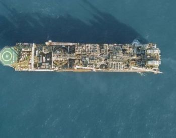
Åsgard B platform
Location
Norwegian Sea
This study was performed by Vysus’ Engineering Dynamics team
Client Challenge
For some time, the Åsgard B platform had experienced serious and repetitive fatigue failures on its exhaust ducts. One serious incident, where a piece broke off the exhaust duct wall, led to venting 500 degrees of hot exhaust gas to the surroundings. Equinor wanted to act comprehensively. Our client invested in a full mechanical failure investigation and a complete redesign of their gas turbine exhaust ducts to prevent future failures.
As part of Equinor's troubleshooting team, we were asked to carry out a mechanical failure analysis. This work was key to identifying and describing the physical mechanism at the root of the problem and ensuring that the new design wouldn’t experience similar failures. Findings from our thorough analysis were needed in just four months.
How we helped
Our analysis covered five interconnected stages.
Initial measurements
The nature of the failure indicated that it was caused by excessive vibrations in the duct walls. Our job was to find out what had caused the duct to vibrate. Several tentative failure hypotheses were proposed, relating to structural integrity, direct excitation by flow and excitation by pressure waves (sound) generated in the gas turbine. These hypotheses were the basis of a field measurement campaign on the exhaust duct.
The measurements ruled out the hypotheses related to pure structural excitation and excitation by noise; the frequencies of the duct vibrations did not match the frequencies we would expect to have seen if these hypotheses were valid. This left us with the hypothesis that the exhaust duct vibrations were excited by fluctuations in the flow at low frequencies, exciting a natural (resonant) frequency of the duct walls.
Fluid-structure interaction modelling and analyses
The measurements had exposed a complex problem. To solve it, we needed a deeper understanding of the physical mechanisms behind it. This required modelling the exhaust duct to know how the flow and structure were behaving in the current design.
- First, we carried out a set of 3D computational fluid dynamics (CFD) analyses, both steady and unsteady, of the flow in the exhaust duct. These gave a clear indication of large unsteady fluctuations at relatively low frequencies.
- Second, we used the finite element method (FEM) to model and analyse the structure of the exhaust duct in relation to stress distribution, mode shapes and natural frequencies. This showed that part of the duct walls had low natural frequencies within the same range as the frequencies of the unsteady flow fluctuations.
- We then combined these two models in a coupled, fluid-structure interaction (FSI) calculation. By using this technique, we could transfer the unsteady fluid loading onto the vibrating duct structure, giving a clear picture of exactly how and where the flow affected the structure. We then carefully verified and calibrated the FSI model with the measurement results to make it as accurate as possible.
Our model confirmed our initial hypothesis that large fluctuations in the flow were exciting natural frequencies of the duct walls. The consequent high vibration levels led to corresponding high levels of stress, which in turn caused the fatigue failure.
Design evaluation
Having created a model that accurately predicted how the flow and structure behaved in the current exhaust duct, we used this to predict how they would behave for the new design proposals – ensuring that the chosen solution would prevent future failures. Equinor was considering two different design proposals for the new exhaust duct. Based on the information from our model, we were now able to evaluate the design proposals and recommend the one best suited. Equinor chose the Mjørud design as this reduced both the large and unsteady fluctuations in the flow and showed much fewer problematic low frequency structural modes. Our analysis helped refine the design; it had shown a low frequency resonance problem that required further modifications of the lower part of the exhaust duct.
Design improvement
We considered several design features to solve the low frequency resonance problem. Our focus was to increase the lowest natural frequencies of the duct walls, so they wouldn’t be excited by the low frequency pressures created by the unsteady fluctuations in the flow. This was done by introducing a top circular section of the lower transition cone. We also discovered a new way of improving the structural damping, namely by compressing the thermal insulation material that was used on the cone. This reduced the amplitude of the vibrations, helping to reduce the stress on the duct walls.
Final measurements
After evaluating and improving the final design, the exhaust ducts were installed on the Åsgard B platform. To make sure that the new design was behaving as predicted, we carried out final measurements of the exhaust ducts, similar to the initial measurement campaign. The results showed that, not only had the damping improved, but there had also been a very large reduction in the vibration levels. Most importantly, the vibration levels at the natural frequencies were dramatically reduced by a factor of more than 30.
Variable Results
The investigation showed that large fluctuations in the flow excited the natural frequencies of the walls of the exhaust duct (structural resonance excited by large fluctuations in flow). The work helped our client to select and modify the redesigned solution. This fine tuning reduced fluctuations in the flow, raised the lowest natural frequencies of the duct walls and increased the damping, solving the resonance problem.
A thorough evaluation of the new design proposals and a subsequent design improvement meant that vibration levels in the final exhaust duct were reduced by a factor 30.
Related Services

